You hear this term jitter quite a lot in audiophile discussions, particularly with reference to digital audio conversions or DACs. Yuri ends the year with a more detailed explanation of what jitter actually is, measured, and suppressed in audio components.
This article was reproduced from the educational archives of Yuri’s Sample Rate Converter website with his kind permissions. All copyright belongs to said website and any reproduction of this information below can only be done with the express permission of Yuri Korzunov.
What is jitter?
Jitter is the time distortions of recording/playback of a digital audio signal. Many audiophile digital audio system owners worries about jitter. Below we will discuss why jitter exists, who it is estimated, and suppressed.
Digital-analog converters (DAC) transform sample sequences (digital values) to analog voltage level sequences. In the ideal case, the same time distance between the samples should be provided. The distance is defined by what we call clocking. However, clocking in not ideal and the restored signal is distorted like it is shown in the picture.
Jitter is thus a deviation of time between the digital and analog samples (deviation of the sampling rate).
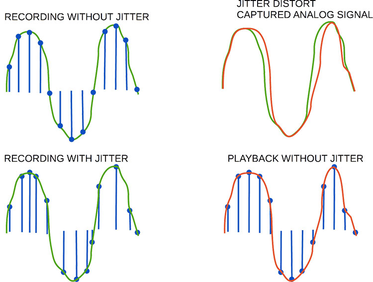
Jitter time distortions of playing back digital signal

At the upper left part of the picture, we can see the original musical signal (green) captured into digital form. At the bottom left part of the picture we can see the restoration of the captured digital signal back to analog form.
The samples (vertical lines with a dot) have unstable time position (jitter) on the horizontal axis. Thus the restored signal is distorted. We can see this distortion in the right part of the picture.
How does jitter appear?
Jitter is a sample clock issue (clock deviation). Jitter appears in a moment when the electrical digital signal inline (wires) is transformed into a binary sequence.
How the jitter appears [bit value (0/1) detection]

To transmit music data through a line (cable), a digital bit sequence is converted to electrical form. Coding in the electrical form may be implemented in different ways (voltage level values or other).
Here we consider simple amplitude coding: signal voltage level above the threshold (dot line in the picture) is binary value 1, below is binary value 0.
The line transmitter device converts binary data to electrical levels. The line receiver device converts electrical levels back to a binary sequence. And the clock reference moments are the points where the voltage level gets higher in the threshold.
The line transmitter generates a signal close to the square. In the line signal “lose” of form occurs due to noise, frequency, and non-linear distortions. Thus clock reference moments, detecting in the line receiver, may be offset from their initial time position (time deviation at the picture).
Below we will consider where the jitter penetrates into the audio system.
How to measure jitter
Jitter is a non-linear distortion. To measure jitter need put pure sine to the input of a known system.
Scheme of the jitter measurement

At the system output, we check artifacts (harmonics) and noise.
Jitter spectrum

Jitter products (artifacts and noise) depends on the input signal. To check the dependency we can take a spectrum analysis of different input signal level and frequencies.
The picture is not a real spectrum. It is only an illustration for better understanding.
We can measure:
- a full system
- ADC’s digital output by a spectrum analyzer
- DAC’s analog output by a mathematically modeled sine
Measurements #2 and #3 allow us to identify separate errors within individual system parts.
Jitter vs delay
Jitter is a deviation time between samples. Delay is shifting of a full signal waveform but keeping time distance between samples.
Jitter vs latency
Latency is a delay for processing inside an audio device (read below about a FIFO buffer).
What are the reasons for jitter?
Above we considered, that clock deviation is an effect of digital signal distortions.
There are several factors that impact on clock deviation:
- clock generator instability
- noise in the digital audio signal line
Clock generators have electronic elements, that define the frequency and its deviation. Changing the power DC voltage can cause frequency deviations of the clock generator. Power supply units can generate noise into electrical lines. This noise can modulate the generated clock impulses.
The modified clock signal causes the time deviation (see the picture).
Noise, that impact on the digital audio signal line, penetrates from electrical circuits and the air.
Total system jitter issue
Unfortunately, jitter is not a pure DAC issue. When we use recorded stuff, we already have a jittered sequence of digital samples.
To understand jitter issues fully we need to learn more about the full recording-playback system.
- The first jitter source can be a clock generator of an analog-digital converter (ADC)
- Then digital signal pass thru the digital audio system without time errors
- Digital music signal comes to DAC and converted to analog with time errors (read details below).
Jitter into full audio system

Capturing of music is the periodical measurement of an analog signal. If the periods will vary, it causes time distortions in recorded audio samples.
Jitter in an audio recording. Let’s compare capturing with jitter and without
In the upper left part of the picture, the signal is captured without jitter.
In the lower-left part of the picture, the signal captured with jitter.
We can see that samples for both of these cases have different values. I.e. after restoration to analog form (playback) signal, captured with and without jitter, they have different waveforms of the analog signal.
If music was recorded with jitter errors we can’t compensate it further. Because the jitter is random. As a rule, in a recording studio, we use professional apparatus, including dedicated clock sources, (a Word Clock as an example). Therefore, engineers in the studios aim for a maximum decrease in losses with the best possible clocking devices.
The digital domain between ADC and DAC
Let’s look at point #2 (digital signal pass through the digital audio system).
When a signal is placed into the digital domain (signal in digital form) jitter does not matter. Because time scores for binary signal form have pure mathematical values with infinite precision. Any delays in processing between samples do not matter for a restored signal.
However, processing delays in the digital domain can cause real-time interruptions of the data stream that feeds the DAC. But it is not a jitter issue. Read the details below.
Clock schemes and jitter
Now let’s look at point #3 (signal come to DAC from pure digital part of the audio system).
Points of audio jitter impact

Noise, that cause jitter, penetrate to digital signal several ways from:
- a computer power supply unit (PSU) to digital audio interface clock generator,
- a computer power supply unit through a digital audio interface to a digital audio cable,
- air to the digital audio interface of a DAC device,
- DAC PSU to a DAC’s digital interface,
- DAC PSU to a DAC-chip,
- DAC clock generator,
- DAC PSU to a DAC’s clock generator.
However, FIFO buffers provide “jitter isolation” between any “jittered” segment.
FIFO (“first input, first output”) kind of buffer (array of number samples) samples out from the buffer on a ‘first-come-first-served’ basis.
Putting and getting samples to/from the buffer are asynchronous. Clocks of buffer writing and reading are independent. A FIFO buffer causes a time delay between sample input and output (latency). Latency is measured in the seconds, milliseconds, microseconds.
Short buffers cause small delay values. Short latency is important for real-time audio systems, used for music live performance and production. For home audio, a big latency value almost does not matter, except real-time sound adjusting.
FIFO buffer with asynchronous writing (input) and reading (output). Sample move thru buffer step-by-step

Jitter before a FIFO-buffer does not impact the clock after FIFO because the buffer is asynchronous. Therefore, there are no reasons to worry about jitter before FIFO into the DAC at the scheme in the picture above.
For an audio system, before suggesting effective jitter suppression methods, it is better to learn the scheme of the improved system.
In most cases, asynchronous FIFO buffer corrects interruptions in a binary data stream. Of course, significant interruptions can’t be fixed by FIFO. The non-fixed interruptions cause pauses, clicks, or other sound damages. It happens when the buffer is empty and no binary data is ready for conversion to analog form.
DAC clock and jitter
DAC clock synchronization has 3 options:
- by the DAC digital interface (SPDIF, as an example)
- by the internal clock generator
- by an external dedicated clock generator
Below we consider cases for a DAC with internal FIFO of input audio data.
Synchronization by the digital interface has jitter sources:
- in a clock generator and PSU of the digital line transmitter
- air noise impact to the signal via cable signal transmission
- The PSU of the DAC
Synchronization by DAC’s internal clock generator has primary jitter sources:
- the clock generator itself
- the PSU of a DAC
Synchronization by external dedicated clock generator has jitter sources:
- the external clock generator and its PSU;
- air noise impact to the clock signal during transmitting via the cable;
- PSU of DAC.
For home applications, I’d recommend using a DAC’s internal clock generator as the simplest way. It may be chosen in the DAC’s settings.
However, it does not guarantee the best result. Each setup should be analyzed (measured) to choose the minimal jitter configuration.
Conclusions
- The jitter effect occurs only during the transformation digital to analog signal or back.
- Jitter can’t distort the signal in the digital domain. Jitter can’t distort a signal in the analog domain.
- Jitter may be measured by distortions of the input test sine of the analyzed music system.
- FIFO asynchronous buffer isolates the system parts from jitter.
- As rule, if DAC’s internal or external dedicated clock generator is used for synchronization, jitter suppressing before a DAC’s digital input is not sensible.
- If a DAC uses synchronization by the digital audio input, jitter suppressing before DAC makes sense.
- The most effective jitter suppressing may be achieved after analysis of the audio system scheme (including device schemes) and measurements.